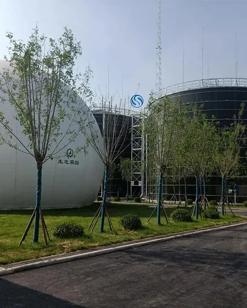
When an owner orders Custom GFS Tanks, the most expensive mistakes often begin with three lines on a drawing: the inlet, outlet, and overflow. This guide explains how to specify inlet outlet overflow connections for water storage tanks, including GFS tank connection sizing and overflow pipe design for bolted steel tanks. The design must match the hydraulic grade line, potable water storage requirements, fire water tank duty, operating level, freeboard, maintenance access, and local code. A Wansheng quotation should therefore be based on a dimensioned connection schedule rather than a tank volume alone.

Tank capacity does not determine connection size by itself. A 500 m³ tank may receive water slowly from a treatment plant, rapidly from a fire pump, or intermittently from a roof drainage system. Each duty produces different flow velocity, pressure loss, valve requirements, and overflow capacity.
The connection schedule should define:
- Connection service: inlet, outlet, drain, overflow, scour, bypass, or sampling.
- Design flow in m³/h or L/s.
- Nominal diameter, flange standard, pressure class, and facing.
- Connection centerline elevation measured from the finished foundation or tank bottom.
- Pipe orientation, nozzle projection, internal fitting, external valve, and dismantling joint.
- Normal water level, maximum operating level, overflow level, and emergency level.
- Material compatibility with the stored water and coating system.
- Access, isolation, inspection, and cleaning requirements.
For glass-fused-to-steel tanks, factory-installed openings are normally preferred. Field drilling or cutting can damage the glass coating and create corrosion points unless the tank manufacturer provides an approved repair procedure. Wansheng or another qualified supplier should review every opening before fabrication.
Why gfs Water Storage Tanks Need a Connection Schedule
Preparation for Custom GFS Tanks Connection Design
Prepare the following information before requesting a quotation or final drawing:
- Tank working volume and geometric dimensions.
- Normal, minimum, maximum operating, and emergency water levels.
- Inlet design flow, including the highest credible filling rate.
- Outlet design flow, including peak demand, fire flow, or pump suction duty.
- Available upstream pressure and downstream pressure.
- Pipe material, internal diameter, route length, fittings, and elevation changes.
- Water temperature, pH, chlorination level, and whether the water is potable, process, wastewater, or fire protection water.
- Applicable local plumbing, structural, potable-water, and fire codes.
- Flood level, seismic design category, wind exposure, and site drainage conditions.
Collect the hydraulic and operating data for gfs Water Storage Tanks
Use a calibrated tape measure or laser distance meter, survey level, pipe schedule, P&ID, general arrangement drawing, hydraulic calculation sheet, flange standard, valve datasheet, and the tank manufacturer's nozzle template. For larger facilities, a pressure-loss calculation should be checked by the responsible mechanical engineer.
Useful references may include AWWA D103 for factory-coated bolted steel tanks, NFPA 22 where the tank serves fire protection, local drinking-water requirements, and the project specification. These references do not replace the authority having jurisdiction or the project engineer's approval.
Tools and documents for Custom GFS Tanks
How to Specify Inlet Connections for gfs Water Storage Tanks
Tools: Pump curve, flow meter data, process design basis, calculator, and hydraulic model.
Action: Record the normal and maximum filling flow separately. If the inlet is controlled by a float valve, altitude valve, or level-control valve, use the valve's maximum rated flow and its minimum available differential pressure. If a pump fills the tank, use the operating point that can occur during simultaneous pump operation, not only the preferred point.
Parameters: State flow in L/s or m³/h, upstream pressure, downstream water level, valve type, and allowable velocity. Do not select a nominal diameter from tank volume alone. Calculate velocity using
Check: Confirm that the selected pipe and valve can pass the maximum flow without excessive head loss, noise, vibration, or water hammer. Check the valve manufacturer's minimum and maximum differential pressure.
Failure fix: If the inlet does not achieve the required filling time, first check actual internal diameter, valve pressure loss, strainer blockage, and pump duty. Increasing the tank nozzle without checking the upstream pipe will not correct an undersized supply main.
1. Establish the inlet design flow
Tools: Tank elevation drawing, survey datum, level schedule, and nozzle orientation sketch.
Action: Specify the inlet centerline from a fixed datum, such as the top of the concrete ring beam, finished foundation, or tank bottom. Show whether the inlet enters through the shell, roof, or floor. For a shell nozzle, indicate the shell course and angular position. For a roof inlet, show the support and penetration detail.
Parameters: Define the inlet termination relative to the normal minimum water level. An inlet that discharges above the water surface may introduce air and splashing; an inlet that discharges below the water surface may require backflow protection or a suitable internal diffuser.
Check: Confirm that the inlet cannot create a short-circuit directly to the outlet, disturb level sensors, or scour the tank floor. Review the velocity at the internal diffuser and the available clearance for inspection.
Failure fix: If turbulence, vortexing, or air entrainment appears during commissioning, install or revise an approved internal diffuser, reduce the inlet velocity, alter the discharge direction, or revise the control sequence. Do not weld directly to a glass-fused panel without manufacturer approval.
2. Set the inlet elevation and discharge direction
Tools: Flange standard, gasket chart, valve datasheet, pipe support detail, and manufacturer's nozzle schedule.
Action: State nominal pipe size, flange drilling, pressure class, facing, gasket material, bolt material, valve type, and whether a dismantling joint is required. Show the external isolation valve and any check valve, strainer, air-release valve, or flow-control valve.
Parameters: The flange rating must suit the design pressure and temperature. The valve must be accessible without removing tank panels. The pipe must have independent supports so that its weight, thermal movement, and thrust are not transferred to the tank shell.
Check: Review the nozzle load limits supplied by the tank manufacturer. Check bolt access, gasket compatibility, flange alignment, and drainability.
Failure fix: If the field pipe does not align with the nozzle, do not force the flange into position with bolts. Use a properly selected dismantling joint, flexible coupling, or revised pipe support arrangement after confirming the manufacturer's allowable loads.
3. Specify the inlet nozzle, flange, and valve assembly
How to Specify Outlet Connections for Custom GFS Tanks
4. Define the outlet duty and pump suction condition
Tools: Demand profile, pump datasheet, suction calculation, pipe profile, and water-level schedule.
Action: Identify whether the outlet serves gravity distribution, a booster pump, fire pumps, process equipment, or a combined system. State normal, peak, and emergency withdrawal rates. If pumps draw directly from the tank, calculate the available net positive suction head using the lowest operating water level.
Parameters: The calculation should include tank water-surface elevation, outlet centerline, suction pipe losses, strainer losses, valve losses, and pump required NPSH. The lowest usable water level must be defined; it is not necessarily the tank floor.
Check: Confirm that the pump's available NPSH exceeds the required NPSH by the margin specified by the pump engineer. Check that the outlet does not form a vortex at the minimum water level.
Failure fix: If the pump cavitates or loses prime, investigate insufficient submergence, excessive suction velocity, blocked strainers, air leaks, and an outlet elevation that is too high. A vortex breaker or anti-vortex plate may be required, but its geometry must be approved for the tank and flow condition.
5. Locate the outlet to preserve usable storage
Tools: Tank section drawing, minimum operating level, sediment allowance, and maintenance plan.
Action: Set the outlet centerline above the sediment or scour allowance and below the minimum operating water level, while preserving sufficient submergence for the design flow. If the outlet is intended to drain almost the entire tank, provide a separate low-level drain or scour connection rather than lowering the main suction indiscriminately.
Parameters: Show the outlet elevation, internal anti-vortex arrangement, external isolation valve, drain point, and access clearance. For potable water, specify materials and seals approved for contact with drinking water under the applicable jurisdiction.
Check: Confirm that maintenance staff can isolate the outlet and that the remaining water volume is compatible with cleaning and disinfection procedures. Verify that the outlet does not interfere with tank floor slope, internal columns, ladder access, or level instrumentation.
Failure fix: If sediment reaches the outlet, review inlet turbulence, tank turnover, floor drainage, and cleaning intervals. Do not rely on a screen alone to solve a poor outlet location; screens can increase head loss and become blocked.
6. Separate service outlets where the risk assessment requires them
Tools: Process flow diagram, water-quality plan, fire-protection review, and isolation schedule.
Action: Separate potable, process, fire, drain, and sampling services when cross-connection or operational isolation is a concern. A combined outlet may be acceptable only when the hydraulic and regulatory review confirms that one service cannot compromise another.
Parameters: Identify each line by service, normal status, valve lock position, flow direction, and connection standard. Where fire protection is involved, follow the approved fire-water arrangement and the authority having jurisdiction.
Check: Verify backflow prevention, cross-connection control, access to locked valves, and the ability to keep required fire storage unavailable for non-fire use when required by the project.
Failure fix: If operators cannot distinguish service lines, revise the P&ID, pipe labels, valve tags, and physical routing. Clear identification is a control measure, not merely a drafting preference.
How to Specify Overflow Connections for gfs Water Storage Tanks
7. Establish the overflow level and freeboard
Tools: Tank section, control philosophy, rainfall or inflow study, and survey datum.
Action: Define the normal operating level, high-level alarm, high-high shutdown level, overflow invert, and tank roof or shell safe limit. The overflow must be lower than the level at which water could reach an unprotected roof penetration, roof access, vent, or structural component.
Parameters: Freeboard is the vertical distance between the maximum permitted water level and the relevant tank limit. It must account for control-valve closure time, inflow continuing after a pump stop command, wave action, and any site-specific seismic or operational condition.
Check: Confirm that the high-level alarm and shutdown occur before overflow under normal controls, while the overflow remains available as an independent passive safeguard.
Failure fix: If the calculated closing time can raise the water level above the available freeboard, reduce valve closure time only after checking water hammer, add a second level protection device, lower the control setpoint, or increase overflow capacity.
8. Size the overflow for the credible maximum inflow
Tools: Inflow schedule, hydraulic calculation, pipe roughness data, discharge route survey, and local drainage requirements.
Action: Size the overflow for the highest credible inflow when the tank is full and the normal level-control system has failed. Include inflow from pumps, gravity mains, automatic valves, rainwater collection, and any parallel source that can remain open.
Parameters: State the design overflow flow, pipe internal diameter, invert elevation, discharge point, downstream water level, and allowable surcharge. Calculate capacity using an appropriate open-channel or full-pipe method. The discharge route must not return contaminated water to the tank, undermine the foundation, flood electrical equipment, or create an uncontrolled public hazard.
Check: Verify capacity at the actual available head above the overflow invert, not at an assumed pressure. Check screens, grilles, bends, outlet losses, downstream tailwater, and blockage risk.
Failure fix: If the overflow capacity is insufficient, use a larger pipe, multiple overflow branches, a separate emergency overflow, or a revised discharge arrangement. A smaller overflow with a decorative screen is not an acceptable substitute for hydraulic capacity.
9. Detail the overflow termination and protection
Tools: Site drainage plan, vector-control requirements, access and maintenance plan, and overflow detail.
Action: Terminate the overflow where operators can see and inspect discharge. Provide a visible air gap or approved free discharge where required. Install a corrosion-resistant screen or flap arrangement only when it does not reduce capacity or create a blockage hazard.
Parameters: The termination must prevent birds, insects, rodents, surface water, and backflow from entering the tank. The outlet should be protected against erosion and connected to a drainage system sized for the overflow event.
Check: Perform a physical inspection of the screen area, discharge channel, erosion protection, and downstream invert. Confirm that the outlet remains above the design backwater level when required by code.
Failure fix: If the overflow discharges below a flood or drain level, revise the termination, provide an engineered backflow arrangement, or obtain written approval from the authority having jurisdiction. Never assume a check valve alone provides a safe potable-water air gap.
Documented Lessons and User Cases for Custom GFS Tanks
Case lesson: published finished-water storage guidance
A useful verification-based lesson comes from public finished-water storage inspection guidance published by the U.S. Environmental Protection Agency and from AWWA tank inspection practice: inspectors focus on overflow protection, screened openings, sanitary separation, roof and vent condition, and evidence of water entering through unintended routes. The lesson is practical—an overflow is not only a pipe-size item. Its termination, screening, discharge visibility, and protection from backflow are part of the sanitary barrier.
This is intentionally not presented as a fabricated personal story or as a project-specific performance claim. Before publication of a project case, the owner name, tank volume, connection sizes, measured flows, and commissioning records should be verified against the owner's documents. Wansheng project references should likewise be quoted only from an approved project sheet or client-authorized case study.
Field operator scenario: connection information that prevents rework
Operators commonly discover connection problems during installation rather than during design review: the inlet flange is at the wrong elevation, the outlet valve cannot be reached, or the overflow discharges toward the foundation. These are predictable coordination failures. A signed nozzle schedule showing centerline elevation, orientation, flange drilling, valve access, internal fitting, and discharge route gives the installer a checkable reference before steel fabrication.
For a real project, record the operator's name or role, date, measured flow, water level, pressure, photographs, and corrective action. Do not replace those records with unverified claims such as “the tank filled faster” or “the pump became more efficient.”
Common gfs Water Storage Tanks Connection Errors and Fixes
Using tank volume to choose pipe diameter
Problem: A nominal pipe size is copied from another tank with a different filling or withdrawal rate.
Fix: Start with design flow, calculate velocity and head loss, then verify valve and pump duty. Record the assumptions in the connection schedule.
Giving elevations without a common datum
Problem: “Inlet at 2 m” is unclear because the reference may be the foundation, tank bottom, shell ring, or grade.
Fix: State the datum explicitly and include a section drawing with normal, maximum, emergency, and overflow levels.
Field-cutting glass-fused panels
Problem: An opening is added after fabrication without a coating repair method.
Fix: Freeze the nozzle schedule before fabrication. If a change is unavoidable, obtain the tank manufacturer's written repair and sealing procedure.
Allowing pipe loads on the tank shell
Problem: Misaligned or unsupported pipework imposes bending, weight, or thermal loads on the nozzle.
Fix: Add independent supports, flexible connections where justified, and a nozzle-load review. Never use flange bolts to pull a pipe into alignment.
Installing the overflow without checking downstream flooding
Problem: The overflow is hydraulically large enough but discharges onto the foundation, into a flooded drain, or near electrical equipment.
Fix: Check the full discharge path, tailwater level, erosion protection, inspection access, and flood conditions. Show the overflow route on the civil drawing.
Relying on the level sensor as the only overflow safeguard
Problem: A failed sensor, stuck valve, or power outage allows continued inflow.
Fix: Retain a passive overflow sized for the credible maximum inflow and provide independent high-level protection where the risk assessment requires it.
Final Review Checklist for Custom GFS Tanks
Before approving the tank fabrication drawing, verify the following:
- Every inlet, outlet, overflow, drain, scour, vent, and sampling connection has a unique tag.
- Each connection has a service, design flow, nominal size, flange standard, pressure class, material, and gasket specification.
- Centerline elevations and angular orientations use a stated datum.
- Normal, minimum, maximum, high-alarm, shutdown, overflow, and emergency levels are shown together.
- Inlet and outlet calculations include actual pipe losses, valve losses, and operating levels.
- Pump suction calculations include minimum water level and NPSH requirements where applicable.
- Overflow capacity covers the maximum credible inflow and the downstream route is safe.
- Nozzle loads, pipe supports, dismantling joints, and thermal movement have been reviewed.
- Internal diffusers, anti-vortex devices, screens, and ladders do not obstruct one another.
- Potable-water materials and backflow protection comply with the project and local requirements.
- Factory openings are frozen before fabrication, and any later change has written manufacturer approval.
- Commissioning tests include valve operation, level alarms, filling, withdrawal, overflow discharge observation, and leak inspection.
Summary: Specify gfs Water Storage Tanks by Duty, Level, and Risk
The correct inlet, outlet, and overflow specification begins with flow and operating levels, not tank volume. Define the hydraulic grade line, set elevations from a common datum, protect the GFS coating, support external pipework independently, calculate overflow capacity for the credible maximum inflow, and inspect the discharge route. A clear connection schedule gives Wansheng or any qualified fabricator the information needed to produce the right nozzles and helps the site team install and commission the tank without avoidable rework. The core long-tail requirements remain how to specify inlet outlet overflow connections for water storage tanks, GFS tank connection sizing, and overflow pipe design for bolted steel tanks, supported by sanitary protection, hydraulic grade line control, and potable water storage practice.