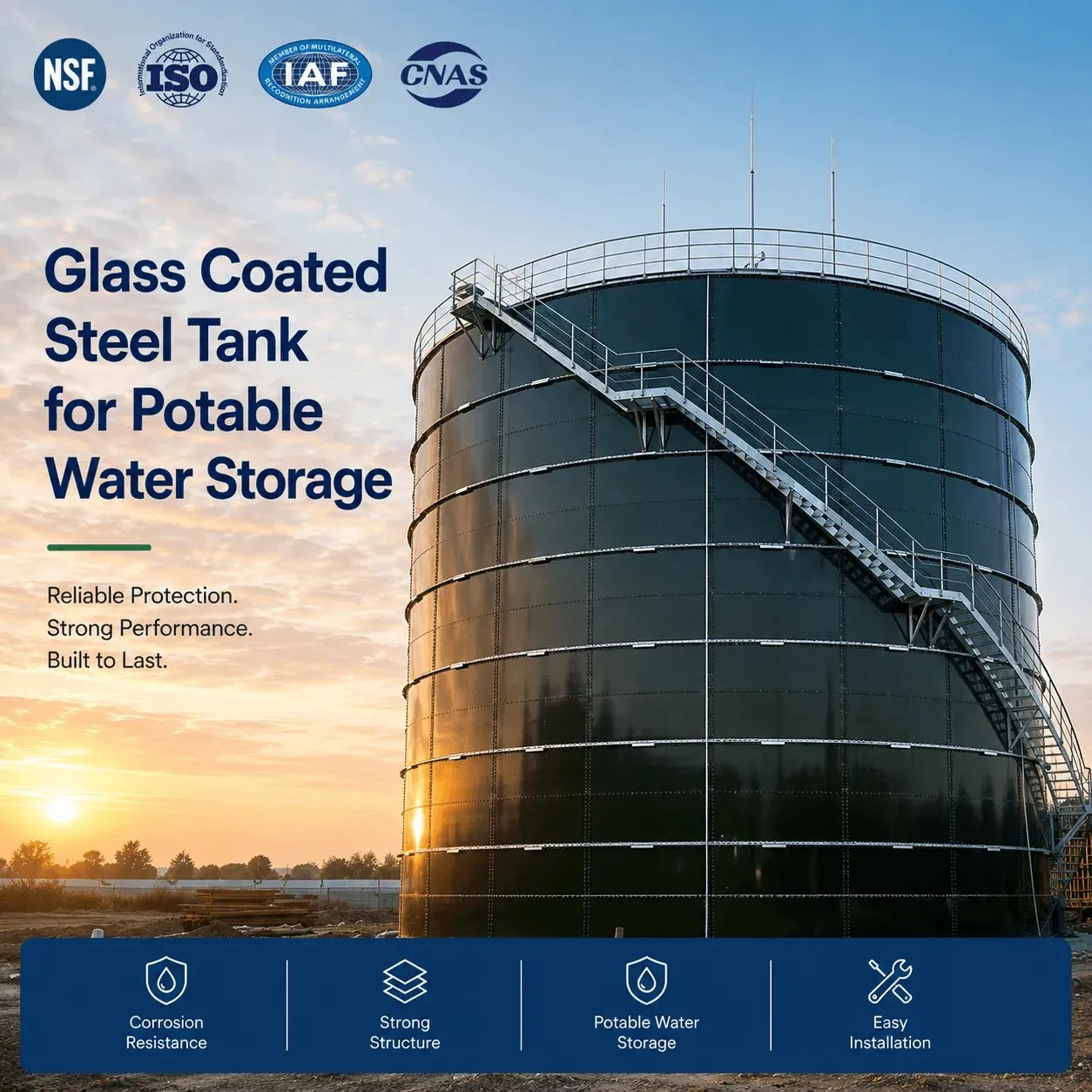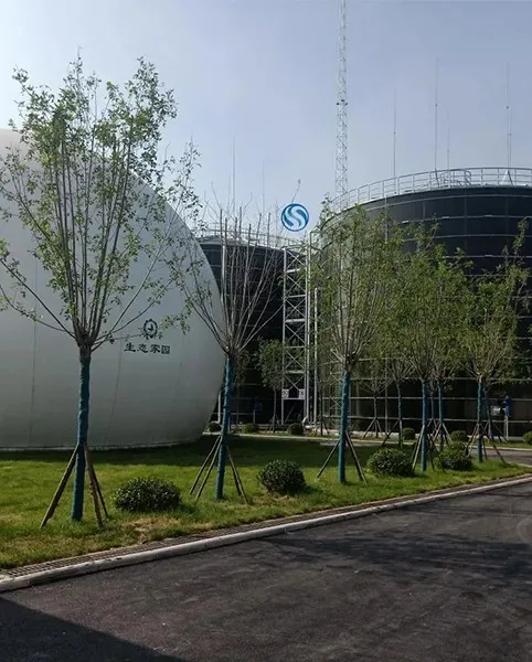
Specifying a potable water storage tank involves much more than selecting a required volume and asking a supplier for a quotation. The tank must fit the hydraulic requirements of the water system, protect stored water from contamination, withstand site-specific structural loads, integrate with piping and controls, and remain practical to inspect and maintain throughout its operating life.
For municipal water utilities, EPC contractors, consulting engineers and industrial project owners, GFS water storage tanks are increasingly considered where modular construction, corrosion resistance and on-site bolted assembly are important project requirements.
However, the term “GFS tank” alone is not a complete technical specification.
Two tanks with the same nominal capacity can differ significantly in plate design, structural calculations, coating quality, sealing system, roof configuration, nozzle arrangement, foundation requirements and potable-water compliance.
This guide explains the major items engineers should define before issuing an RFQ or approving a GFS potable water tank proposal.
1. Start With the Water Storage Duty, Not the Tank Diameter
One of the most common mistakes during early procurement is requesting a tank based only on a nominal capacity:
“1,000 m³ potable water tank required.”
That is not enough information for an engineered storage system.
Before determining tank dimensions, engineers should define what the stored volume is intended to accomplish.
Typical potable water storage duties include:
balancing daily demand;
providing peak-hour supply;
maintaining emergency reserves;
supporting pressure zones;
maintaining water supply during pump or power interruption;
providing operational storage for treatment facilities;
supporting remote communities;
storing treated water before distribution.
The usable storage requirement should therefore come from the hydraulic design of the entire water system rather than an arbitrary tank size.
A simplified design relationship is:
Required Storage Volume = Operational Storage + Emergency Reserve + Other Required Reserve
The exact method varies according to local regulations, utility standards and system configuration.
Engineers should also distinguish between:
Nominal tank volume – the theoretical geometric capacity of the vessel.
Operating volume – the normal usable volume between control levels.
Effective water volume – the water actually available after considering freeboard, low-level restrictions, outlet elevation and unusable bottom volume.
A project that genuinely requires 1,000 m³ of usable water may therefore require a tank with a nominal capacity greater than 1,000 m³.
This should be clarified before tank geometry is finalized.
2. Specify the Required Tank Diameter and Height Based on the Site
Once storage capacity is established, the next decision is tank geometry.
GFS tanks are modular cylindrical structures, so a required volume can often be achieved with different combinations of diameter and shell height.
A wider, lower tank may suit one project, while a narrower, taller tank may be more practical for another.
Engineers should evaluate:
available footprint;
site boundaries;
tank spacing;
nearby buildings;
access roads;
construction equipment clearance;
geotechnical conditions;
piping elevations;
required hydraulic head;
visual restrictions;
wind exposure;
future expansion.
Tank height also affects hydrostatic pressure.
As the water depth increases, pressure at the lower shell courses increases. The lower portions of the tank may therefore require different plate thicknesses or structural arrangements from the upper courses.
For this reason, specifications should avoid requiring one plate thickness for the entire tank unless that requirement has been structurally justified.
A better specification is to require the manufacturer to provide a structural design showing appropriate shell thicknesses for each course based on calculated loads.
3. Define the Applicable Structural Design Standard
The RFQ should state which engineering standard, code or local regulation governs the tank design.
For bolted steel water-storage tanks, engineers may encounter standards such as AWWA D103, depending on the project location and owner requirements. The current AWWA storage standards list identifies D103 for factory-coated bolted carbon steel tanks for water storage.
However, simply writing “tank shall comply with AWWA” is too vague.
The project specification should identify:
applicable standard;
required edition where contractually relevant;
local building code;
wind design criteria;
seismic design criteria;
snow load where applicable;
roof live load;
operating liquid level;
liquid specific gravity;
design temperature;
external environmental conditions.
If the project is outside North America, EN standards, national codes or project-specific structural requirements may apply instead.
The most important point is that the manufacturer must know the design basis before calculating the shell, roof, anchors and foundation loads.
4. Provide Accurate Wind and Seismic Data
Tank design cannot be separated from the installation location.
A GFS potable water tank installed in a low-wind inland region should not automatically use the same structural configuration as a tank installed in a coastal cyclone zone.
The RFQ should therefore provide the project location or the required design parameters.
Important information includes:
basic design wind speed;
exposure category;
terrain category;
seismic design parameters;
site soil classification;
tank importance category;
snow load where applicable;
local temperature range.
For high-seismic or high-wind sites, anchorage can become a major part of the structural design.
The supplier may need to design:
anchor bolts;
anchor chairs;
base ring components;
shell reinforcement;
roof-to-shell connections.
Leaving this information until after the purchase order can result in redesign, additional steel, foundation changes and unexpected cost.
5. Specify GFS Coating Requirements, Not Just “Enamel Tank”
The most important functional difference between a conventional bolted steel tank and a Glass-Fused-to-Steel tank is the protective surface.
A Glass-Fused-to-Steel tank uses factory-prepared steel panels with a vitreous enamel layer bonded to the steel through a controlled firing process.
For potable water applications, engineers should specify the required performance rather than simply writing:
“Tank shall be enamel coated.”
Important coating-related requirements may include:
coating suitability for potable water contact;
coverage of water-contact surfaces;
coating continuity;
corrosion resistance appropriate to the stored water;
testing method;
acceptable defect criteria;
repair procedures for damage occurring during transportation or erection;
inspection documentation.
The coating system should also be compatible with the actual water chemistry.
Engineers should provide available water-quality information where unusual conditions exist, particularly:
pH;
chlorides;
sulfates;
disinfectant concentration;
conductivity;
operating temperature;
other treatment chemicals.
This helps ensure that the proposed tank materials and sealing components are suitable for the real service environment.
6. Potable Water Compliance Must Be Explicit
A tank used for drinking water should not be specified solely according to structural criteria.
Materials in contact with potable water must also satisfy applicable health and regulatory requirements.
For projects requiring NSF compliance, engineers should understand what NSF/ANSI/CAN 61 addresses. The standard establishes health-effects requirements relating to contaminants or impurities that may be indirectly imparted to drinking water from products, components and materials in contact with the water. Its scope includes protective coatings and other drinking-water-system materials.
This distinction matters.
NSF/ANSI/CAN 61 should not be treated as a substitute for:
structural design verification;
hydrostatic testing;
leakage testing;
workmanship inspection;
hydraulic design;
local building-code compliance.
In an RFQ, engineers should clearly identify:
the required potable-water standard;
which tank components are required to comply;
whether certificates or third-party documentation must be submitted;
whether local drinking-water authority approval is also required.
Do not accept a vague statement such as “food grade materials” when the project specification requires a defined drinking-water certification.
7. Pay Close Attention to the Sealant and Bolted Joint System
GFS tanks are assembled from factory-manufactured panels using bolted joints. That makes the joint system a critical part of the final tank.
The specification should address:
bolt material and protective system;
washer arrangement;
bolt head protection;
sealant type;
sealant compatibility with potable water;
joint preparation;
application method;
required curing conditions;
inspection after assembly.
A high-quality enamel panel cannot compensate for poorly prepared or incorrectly sealed joints.
Engineers should therefore evaluate the tank as a complete system rather than reviewing only the coated steel plate.
Questions worth asking during technical evaluation include:
Is the sealant suitable for continuous potable water contact?
How are sealant application and joint compression controlled during erection?
What procedures are used to inspect joints before filling?
How are damaged coating areas around bolts or panel edges addressed?
These details become especially important for tanks expected to operate for decades with minimal leakage-related maintenance.
8. Select the Roof According to Water Quality and Environmental Requirements
Potable water tanks require a suitable cover to protect stored water from external contamination.
The roof system should be selected according to:
tank diameter;
environmental exposure;
structural loads;
maintenance access;
corrosion conditions;
ventilation requirements;
local regulations.
For large-diameter storage tanks, an aluminum geodesic dome roof may be considered where a lightweight, corrosion-resistant roof system is appropriate. AWWA also maintains D108 as a standard specifically addressing aluminum dome roofs for water storage facilities.
Regardless of roof type, engineers should define requirements for:
roof access;
hatches;
ventilation;
insect screens where required;
rainfall exclusion;
overflow protection;
roof drainage where applicable;
load capacity;
safe maintenance access.
The design should minimize opportunities for birds, insects, debris and surface runoff to enter the stored water.
9. Vent Sizing Should Match the Maximum Filling and Emptying Rate
Tank vents are sometimes treated as minor accessories, but they are part of the hydraulic safety of the system.
During filling, air must escape.
During rapid withdrawal, sufficient air must enter.
If the vent is undersized, abnormal pressure or vacuum conditions can develop.
The engineer should therefore provide:
maximum inlet flow rate;
maximum outlet flow rate;
expected simultaneous operating conditions;
required screening or contamination protection;
applicable vent design criteria.
Vent sizing should be based on actual operating flow rather than simply selected according to tank capacity.
This is particularly important when the tank is connected to high-capacity pumps or rapidly changing distribution demand.
10. Define Inlet and Outlet Arrangements to Protect Water Quality
The positions of tank connections influence both hydraulic performance and water quality.
Typical connections include:
inlet;
outlet;
overflow;
drain;
scour connection;
sampling point;
level instrumentation ports;
recirculation connection;
chemical dosing connection where applicable.
Engineers should avoid selecting nozzle locations only according to the easiest piping route.
Poor inlet and outlet arrangements can create stagnant zones and ineffective turnover.
For potable water projects, hydraulic considerations may include:
preventing short-circuiting between inlet and outlet;
improving mixing;
maintaining adequate turnover;
minimizing dead zones;
avoiding sediment accumulation;
allowing full drainage for cleaning.
Where water age is a significant concern, the engineer may need to consider inlet diffusers, mixers or other circulation strategies.
The tank supplier needs the connection schedule early because openings and reinforcement requirements affect panel manufacture.
11. Specify Overflow and Drainage Before Manufacturing
The overflow system must safely handle conditions that could otherwise cause tank overfilling.
Engineers should define:
overflow diameter;
overflow elevation;
discharge location;
screening;
splash protection;
erosion control;
drainage away from the foundation.
Overflow discharge should not create conditions that undermine the tank foundation.
The drain connection should also allow effective tank emptying for inspection, maintenance and cleaning.
A common design problem occurs when the tank drain is specified late and the surrounding site drainage system cannot handle the discharge volume.
Tank drainage should therefore be coordinated with civil design from the beginning.
12. Instrumentation Requirements Should Be Included in the RFQ
Modern water storage tanks often operate as part of an automated distribution system.
The tank specification should therefore identify required instrumentation interfaces.
Possible requirements include:
continuous level transmitter;
high-level alarm;
high-high level alarm;
low-level alarm;
low-low level pump protection;
pressure sensors;
temperature measurement;
access for sampling;
telemetry or SCADA interfaces.
The tank manufacturer does not necessarily need to supply the entire control system, but the required penetrations, brackets and mounting points should be coordinated before the panels are manufactured.
Field drilling or modification of coated panels should be minimized wherever practical because unnecessary site modifications create additional quality-control challenges.
13. Foundation Design Must Be Coordinated With the Tank Supplier
The civil foundation and the tank structure are not independent packages.
Tank reactions depend on:
diameter;
operating height;
total water load;
self-weight;
wind load;
seismic load;
anchorage configuration;
soil conditions.
Before the foundation is finalized, the civil engineer should obtain relevant structural loads and interface requirements from the tank designer.
The project should define:
allowable soil bearing capacity;
settlement limits;
foundation level tolerance;
anchor bolt arrangement where applicable;
concrete strength;
drainage around the tank;
grout or interface requirements;
foundation waterproofing details where required.
A precisely manufactured bolted tank still requires a correctly constructed foundation.
Poor level tolerance or differential settlement can create assembly difficulty and unwanted stress in the tank shell.
For projects requiring coordinated design and installation support, review the available tank engineering and installation services early in the project rather than after civil construction has already been completed.
14. Design for Inspection and Maintenance Access
A potable water tank should not merely be designed to hold water. It should also be designed so operators can safely inspect and maintain it.
Engineers should consider:
external ladder;
internal ladder where permitted;
platforms;
handrails;
roof access;
manways;
shell access openings;
fall-protection requirements;
sampling access;
inspection clearance.
The exact requirements depend on local safety rules and owner procedures.
Access design should allow operators to inspect high-risk areas such as:
roof connections;
shell joints;
nozzles;
overflow components;
sealant;
tank floor or base area.
A tank that is difficult to inspect is more likely to develop maintenance problems that remain unnoticed.
15. Require Factory Quality-Control Documentation
Because GFS panels are factory manufactured, the specification should establish what quality documentation the supplier must submit.
Depending on project requirements, submittals may include:
material certificates;
dimensional inspection records;
coating inspection records;
production batch records;
certificate of compliance;
potable-water certification documentation;
bolt and sealant specifications;
packing list;
installation drawings;
structural calculations.
For major municipal or EPC projects, the specification may also include an Inspection and Test Plan (ITP).
The goal is traceability.
The owner should know what has been manufactured, what has been inspected and what acceptance criteria were applied before the tank components arrive on site.
16. Specify Protection During Packing, Shipping and Storage
Factory coating quality means little if panels are damaged during international transportation or careless storage.
The procurement specification should therefore address:
panel separation;
edge protection;
moisture protection;
packaging suitable for transport method;
lifting instructions;
unloading procedures;
temporary site storage;
inspection after delivery.
The contractor should inspect components promptly after arrival.
Damage should be recorded and evaluated before erection rather than discovered after the affected panel has already been installed.
17. Define Installation Responsibility Clearly
An RFQ should clearly state who is responsible for tank erection.
Common project models include:
manufacturer-supplied tank with contractor erection;
manufacturer supervision with local labor;
manufacturer-provided erection team;
full tank supply and installation package.
Regardless of the commercial arrangement, the specification should define:
required installer qualifications;
supervision responsibility;
erection procedure;
bolt-tightening requirements;
sealant application requirements;
allowable weather conditions during installation;
coating repair procedure;
dimensional tolerances;
inspection hold points.
Installation quality directly affects leak tightness and long-term reliability.
Choosing a technically acceptable tank but treating erection as an uncontrolled general construction activity creates unnecessary project risk.
18. Establish a Clear Commissioning and Acceptance Procedure
The tank should not be considered complete immediately after the last bolt is installed.
The project specification should define the commissioning sequence.
A typical process may include:
visual inspection of shell and roof;
inspection of bolts and sealed joints;
verification of nozzles and accessories;
cleaning of the internal surfaces;
controlled filling;
leak inspection;
correction of identified issues;
final hydrostatic or water-holding test according to project requirements;
draining or disinfection where required;
potable-water commissioning according to local procedures.
For drinking water service, cleaning and disinfection requirements should follow the relevant local water authority or project standard.
The acceptance criteria should be agreed before filling starts.
This prevents disputes between owner, contractor and tank supplier about what constitutes successful commissioning.
19. Ask for the Right Information in a GFS Potable Water Tank RFQ
A technically complete RFQ produces more comparable quotations.
At minimum, engineers should provide the following information.
| Specification Item | Information to Provide |
|---|---|
| Application | Potable/drinking water |
| Required usable volume | m³ or gallons |
| Operating water level | Required maximum and minimum levels |
| Site location | City and country |
| Design standard | AWWA, EN, local code or project specification |
| Wind criteria | Required project design data |
| Seismic criteria | Required project design data |
| Temperature | Minimum and maximum site temperatures |
| Water quality | pH and relevant chemistry if available |
| Potable-water compliance | Required certification/approval |
| Tank geometry | Diameter/height restrictions if any |
| Roof | Required roof type or performance |
| Connections | Inlet, outlet, drain, overflow and instrumentation |
| Access | Manways, ladders, platforms and handrails |
| Foundation | Existing/proposed and geotechnical information |
| Installation | Supply only, supervision or complete erection |
| Testing | Required inspection and water-holding procedure |
| Documentation | Drawings, calculations, certificates and QA records |
This information allows tank suppliers to design against the same project requirements.
Without it, one bidder may quote a substantially different technical scope from another, making a low-price comparison misleading.
20. Do Not Evaluate a Potable Water Tank on Price Per Cubic Meter Alone
For engineered storage tanks, the lowest price divided by nominal capacity is rarely a sufficient procurement metric.
A proper technical-commercial comparison should ask whether each quotation includes the same:
design standard;
structural loads;
potable-water compliance;
roof system;
fittings;
access equipment;
sealants;
fasteners;
anchorage;
engineering;
packing;
installation support;
commissioning support;
documentation.
A cheaper quotation may simply exclude items included by another supplier.
Engineers should therefore complete technical normalization before comparing final prices.
The better question is not:
“Which tank has the lowest initial price?”
It is:
“Which proposal meets the complete design basis with the lowest project and lifecycle risk?”
GFS Potable Water Tank Specification Checklist
Before issuing a purchase order, engineers should be able to answer the following questions:
Is the required usable storage volume confirmed?
Are diameter and height compatible with the site?
Is the governing structural standard clearly stated?
Have wind, seismic and environmental conditions been provided?
Is the coating system suitable for the stored potable water?
Is potable-water certification clearly defined?
Are sealant and water-contact components included in the compliance review?
Is the roof configuration confirmed?
Are inlet, outlet, overflow and drain sizes established?
Are nozzle elevations and orientations shown?
Has tank circulation or water-age management been considered?
Are ventilation requirements based on actual flow rates?
Are instrumentation connections included?
Are ladders, platforms and manways specified?
Has the foundation design been coordinated with tank loads?
Are packing and transportation requirements defined?
Is installation responsibility clear?
Are inspection and testing procedures documented?
Are commissioning and disinfection requirements agreed?
Are all bidders quoting the same technical scope?
If several of these questions remain unanswered, the project is probably not ready for final tank procurement.
Frequently Asked Questions
What information is most important when requesting a GFS potable water tank quotation?
At minimum, provide the required storage volume, project location, application, applicable design standard, wind and seismic criteria, water characteristics, required potable-water compliance, nozzle schedule, roof requirements and installation scope. Site drawings and geotechnical information are also valuable where available.
Is NSF/ANSI/CAN 61 enough to specify a potable water tank?
No. Potable-water material compliance and structural performance address different risks. The project must separately define structural design, environmental loads, hydraulic requirements, accessories, installation quality and commissioning procedures.
Should engineers specify tank capacity or exact tank dimensions?
Start with the required usable capacity and any site limitations. The final diameter and height can then be optimized against hydraulic, structural, construction and footprint requirements.
Why does the project location matter to the tank manufacturer?
The installation location affects wind loading, seismic conditions, temperature, snow loading where relevant, corrosion exposure and potentially the applicable building codes. These factors can change the tank structure, anchorage and foundation requirements.
Should potable water quality be provided to the tank supplier?
Yes, particularly where the water has unusual chemistry or elevated disinfectant, chloride or other relevant concentrations. Material compatibility should be evaluated against actual service conditions rather than assuming all potable water environments are identical.
When should tank nozzles and piping connections be finalized?
Preferably before panel production. Early coordination allows openings, reinforcement and connection locations to be incorporated into manufacturing and reduces the need for field modifications.
Who should design the tank foundation?
The foundation is normally coordinated between the tank structural designer and the project's civil or structural engineer. The tank supplier provides tank loads and interface requirements, while the project engineer designs the foundation according to site geotechnical conditions and local requirements.
Final Engineering Perspective
A reliable potable water tank begins with a complete design basis.
Specifying only “GFS tank, 1,000 m³” transfers too many unresolved engineering decisions into the quotation stage and makes bids difficult to compare.
A stronger specification defines the required usable capacity, operating conditions, structural codes, design loads, potable-water requirements, GFS coating expectations, roof, sealing system, piping connections, ventilation, access, foundation interfaces, installation scope, testing and project documentation.
This approach helps engineers achieve three objectives at the same time:
protect drinking water quality, reduce technical uncertainty during procurement, and lower the risk of expensive changes during construction.
For upcoming municipal, commercial or industrial drinking-water storage projects, Wansheng provides engineered GFS potable water tank solutions with support from technical selection and structural coordination through manufacturing, installation guidance and project delivery—contact us with your required capacity, site location and design conditions to develop a tank solution for your project.