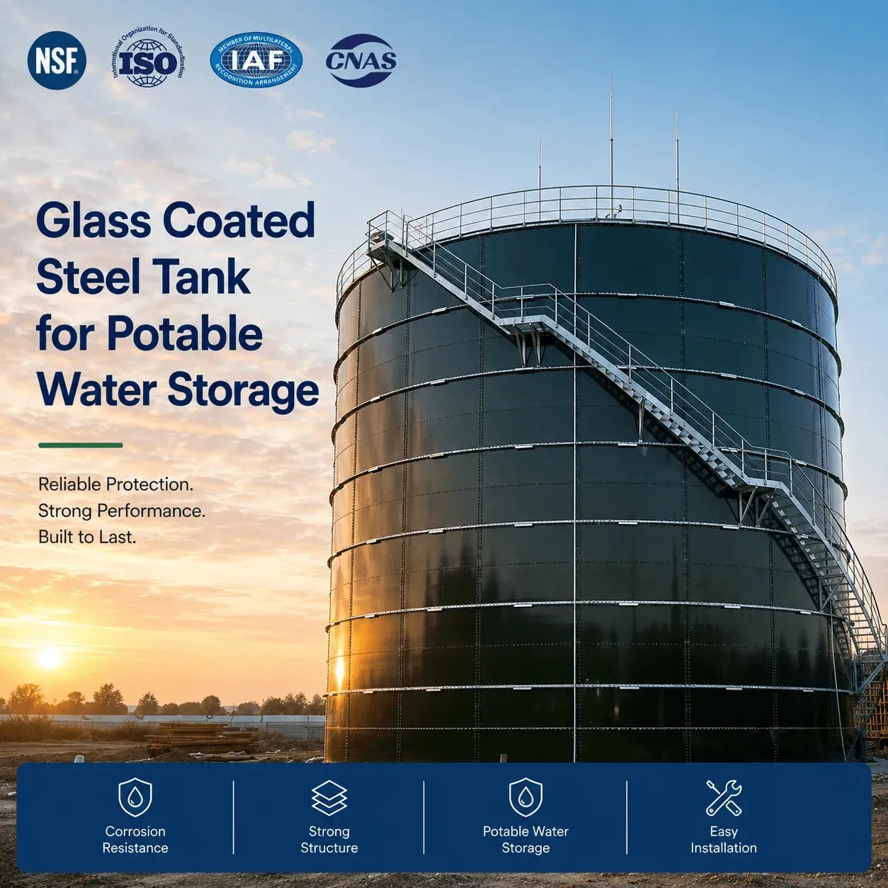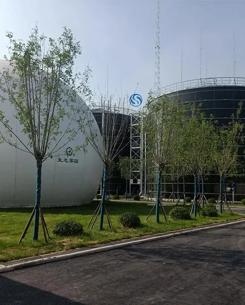
A municipal drinking water storage tank should never be designed as an isolated vessel.
Its performance depends on how it interacts with the treatment plant, pumping stations, pressure zones, transmission mains, distribution network, fire demand, operating controls and daily consumption pattern.
For this reason, designing GFS water storage tanks for municipal drinking water systems requires more than selecting a tank capacity and diameter.
Engineers must answer several interconnected questions:
Where should the tank be located?
What hydraulic function will it perform?
What water levels are required?
How should the inlet and outlet be arranged?
How will water turnover be maintained?
What happens during peak demand or pump failure?
How should overflow and drainage be handled?
What wind and seismic loads must the tank resist?
How will operators inspect and maintain the tank?
How will the system prevent excessive water age?
The following design framework helps municipal engineers, EPC contractors and water utilities evaluate these issues before the tank layout and procurement package are finalized.
1. Define the Tank's Hydraulic Role First
Before deciding tank dimensions, establish what the tank must do in the municipal water system.
Municipal storage facilities commonly perform several functions simultaneously.
These may include:
balancing variations between production and consumption;
supplying peak-hour demand;
maintaining distribution pressure;
providing emergency reserve;
supporting fire-flow demand;
reducing pump cycling;
allowing water production facilities to operate more steadily;
providing temporary storage during maintenance or equipment failure.
Not every tank performs all of these functions.
For example, one reservoir may primarily balance treatment plant output, while another may serve a high-elevation pressure zone.
The design approach will differ.
A tank used for hydraulic pressure support may need a specific water surface elevation, while a tank used mainly for equalization may be optimized more heavily around capacity, water turnover and pumping strategy.
Therefore, the first design document should clearly state:
Primary Function:
For example, municipal potable water equalization and emergency storage.
Secondary Functions:
For example, peak demand support and fire reserve.
Without this definition, later decisions about height, location, piping and control levels can become inconsistent.
2. Coordinate Tank Design With the Hydraulic Model
Municipal water systems are dynamic.
Demand changes throughout the day, pumps switch on and off, valves operate, pressure varies and tanks fill and drain.
For medium and large municipal projects, tank design should therefore be checked against a hydraulic model of the distribution system.
The model can help engineers evaluate:
tank filling rate;
tank drawdown rate;
pressure at critical network nodes;
pump operating hours;
tank cycling;
minimum and maximum water levels;
emergency conditions;
fire-flow scenarios;
future demand scenarios.
A tank that appears sufficient based only on total volume may perform poorly when integrated into the network.
For example, a tank may have adequate storage but be located at an elevation that produces insufficient pressure at the far end of the distribution system.
Another tank may have adequate elevation but fill very slowly because the connecting pipeline is undersized.
Tank design should therefore be evaluated together with the complete hydraulic system.
3. Select the Tank Location Carefully
Tank location strongly affects hydraulic performance.
Important site-selection factors include:
ground elevation;
distance from the demand center;
proximity to transmission mains;
available land area;
access for construction;
future maintenance access;
foundation conditions;
flood risk;
drainage;
environmental constraints;
future development around the site.
Elevation
For gravity-supported systems, elevation directly influences available pressure.
A useful approximate relationship is:
10.2 m water column ≈ 1 bar pressure
The engineer should therefore check the elevation of:
tank foundation;
minimum operating water level;
normal operating level;
maximum water level;
highest customer;
lowest customer.
A tank positioned too low may require booster pumping.
A tank positioned significantly higher than required may create excessive network pressure unless pressure-control measures are installed.
Distance From Demand
A remote tank connected through a small transmission main may not be able to release water quickly enough during peak demand.
Therefore, location and connecting pipe capacity should be evaluated together.
4. Establish Operating Water Levels Before Finalizing Geometry
Tank capacity alone does not define usable storage.
Municipal engineers should establish operating levels such as:
overflow level;
maximum water level;
pump stop level;
normal operating range;
pump start level;
low-level alarm;
emergency reserve level;
fire reserve level;
minimum usable water level.
These elevations influence both storage volume and system pressure.
A typical control philosophy may resemble:
High-High Level
Emergency alarm or inlet shutdown.
High Operating Level
Normal upper operating limit.
Low Operating Level
Triggers additional pumping.
Low-Low Level
Emergency condition or pump protection.
The distance between high and low normal operating levels determines the volume that cycles during everyday operation.
This is important because a tank can have a large total capacity but a relatively small daily turnover volume.
5. Design for Water Turnover, Not Just Storage Volume
One of the most important issues in drinking water storage is water age.
Water should not remain unnecessarily stagnant in a storage tank.
Long residence times can contribute to declining disinfectant residual and other water-quality challenges.
Oversized tanks are particularly vulnerable when actual consumption is much lower than the design demand.
Engineers should therefore evaluate:
Tank Turnover
How much of the stored volume enters and leaves during a normal operating cycle?
Residence Time
How long does water typically remain in storage?
Seasonal Variation
Will turnover decrease significantly during winter, low-demand seasons or early phases of a new development?
A tank designed for a municipality expected to grow substantially over 20 years may initially operate at only a fraction of its future demand.
Possible design responses include:
adjusting normal operating levels;
using multiple tanks instead of one very large tank;
staging future tank construction;
incorporating mixing;
modifying inlet configuration;
improving pump control.
Bigger is not automatically better in potable water storage.
The preferred design balances emergency resilience with sufficient water turnover.
6. Inlet and Outlet Arrangement Is Critical
The locations of the inlet and outlet can strongly influence internal tank circulation.
A poor configuration may allow incoming water to travel directly toward the outlet while other parts of the tank receive relatively little circulation.
This phenomenon is often referred to as hydraulic short-circuiting.
Potential consequences include:
stagnant zones;
uneven disinfectant residual;
long water age in parts of the tank;
sediment accumulation;
inconsistent water quality.
Engineers should consider:
inlet elevation;
inlet direction;
outlet elevation;
horizontal separation;
tank diameter;
expected inlet velocity;
normal turnover;
operating water depth.
A simple inlet and outlet arrangement may be adequate for some tanks.
Other projects may benefit from:
inlet diffusers;
directional nozzles;
separate inlet and outlet locations;
active mixing systems.
The preferred solution depends on hydraulic modeling and project requirements.
7. Avoid Hydraulic Short-Circuiting
Consider a large circular tank where both the inlet and outlet are installed close together.
When water enters the tank, part of it may move rapidly toward the outlet instead of mixing with the full tank volume.
The tank may technically hold thousands of cubic meters, but some stored water may remain much longer than the theoretical average residence time.
A better design attempts to use as much of the storage volume as practical.
Possible strategies include:
Separate the Inlet and Outlet
Increasing physical separation can encourage broader circulation.
Control Inlet Direction
Directing incoming flow may create useful circulation patterns.
Use a Diffuser
A properly designed diffuser can distribute incoming water more effectively.
Install a Mixer
Active mixing can improve uniformity when natural circulation is insufficient.
No single strategy is appropriate for every tank.
The design should consider actual flow rates, dimensions and operating cycles.
8. Consider Mixing Where Natural Turnover Is Insufficient
Some municipal tanks experience strong natural turnover.
Others do not.
Mixing may deserve consideration when:
tanks are oversized relative to current demand;
seasonal demand changes significantly;
temperature stratification occurs;
inlet and outlet geometry creates stagnant zones;
disinfectant residual is difficult to maintain;
hydraulic modeling indicates poor circulation.
Mixing equipment should not simply be added automatically.
Engineers should first identify the underlying hydraulic problem.
If poor turnover results from inappropriate operating levels, changing the operating range may be simpler than installing mechanical equipment.
If tank geometry or piping arrangement creates persistent dead zones, mixing may provide greater benefit.
9. Design the Tank Structure for Site-Specific Loads
Once hydraulic geometry has been established, the tank structure must be designed for its actual site.
For bolted steel water storage tanks, the current AWWA standards list identifies AWWA D103-19 for factory-coated bolted carbon steel tanks used for water storage.
However, engineers should not specify only the standard name.
The tank designer also needs project-specific conditions such as:
tank diameter;
shell height;
maximum liquid level;
water specific gravity;
design wind speed;
seismic parameters;
snow load where applicable;
roof live load;
temperature range;
anchorage requirements;
site exposure conditions.
GFS construction uses factory-manufactured coated steel panels assembled through bolted joints. Shell plate thickness may therefore vary by course depending on the hydrostatic and structural loads.
The lower shell normally experiences greater water pressure than the upper shell.
A properly engineered tank should therefore be structurally calculated rather than designed around one arbitrary plate thickness.
10. Specify Potable-Water-Compatible Contact Materials
Municipal drinking water applications require careful control of materials that contact stored water.
NSF/ANSI/CAN 61 establishes health-effects criteria for materials, components and products in contact with drinking water. It addresses potential contaminants or impurities introduced into the water by those materials.
For a bolted GFS tank, engineers should consider not only the coated steel surface but also other water-contact materials where applicable, such as:
sealants;
gaskets;
joining materials;
coatings;
fittings;
internal accessories.
Potable-water certification should not be confused with structural certification.
A material may meet health-effects requirements but still need separate verification for structural, mechanical and application suitability.
The project specification should therefore clearly identify which drinking-water approvals are required by the local authority.
11. Design the Roof as Part of the Water-Quality Barrier
The tank roof protects the stored drinking water from the surrounding environment.
Roof design should consider:
rainwater intrusion;
insects;
birds;
debris;
sunlight;
wind;
snow where applicable;
inspection access;
ventilation;
structural loads.
For large-diameter municipal storage facilities, an aluminum geodesic dome roof may be considered where lightweight and corrosion-resistant roof construction is appropriate.
AWWA's current standards list identifies D108-19 specifically for aluminum dome roofs used on water storage facilities.
Roof selection should be coordinated with tank diameter and the required openings.
Typical roof components may include:
access hatch;
vent;
level instrumentation;
guardrails;
ladders;
penetrations.
All penetrations should be detailed to minimize the potential for external contamination.
12. Ventilation Must Follow Actual Flow Conditions
As the tank fills, air must leave the tank.
As the tank empties, air must enter.
The vent therefore needs sufficient capacity for the maximum expected filling and withdrawal rates.
The design should consider:
maximum inlet flow;
maximum outlet flow;
emergency withdrawal;
rapid pump operation;
screening;
environmental protection.
An undersized vent can create unwanted pressure or vacuum inside the tank.
A poorly protected vent can also become a pathway for insects, debris or other contaminants.
Vent design is therefore both a hydraulic and sanitary issue.
13. Size the Overflow for Credible Overfill Conditions
The overflow is an important protective feature.
If inlet controls fail or the tank receives more water than expected, excess water must be discharged safely.
The overflow system should consider:
maximum credible inflow;
overflow diameter;
overflow elevation;
discharge routing;
erosion protection;
screening;
drainage around the foundation.
The overflow discharge point should be located where released water will not:
undermine the tank foundation;
flood electrical equipment;
damage access roads;
create unsafe conditions;
return contaminated water toward the tank.
Civil drainage design and tank design should therefore be coordinated.
14. Provide a Practical Drain and Washout Arrangement
Municipal tanks eventually require internal inspection, cleaning or maintenance.
The tank should therefore be capable of being emptied efficiently.
The drain arrangement should consider:
lowest practical drainage point;
drain pipe size;
discharge destination;
site drainage capacity;
sediment removal;
isolation valves.
A small drain may substantially increase tank downtime during maintenance.
However, a large drain releasing thousands of cubic meters rapidly can overwhelm the surrounding drainage system.
The drain should therefore be designed as part of the site infrastructure.
15. Coordinate Tank Connections Before Manufacturing
GFS tank panels are factory prepared.
This means tank penetrations should ideally be established before fabrication.
A municipal tank connection schedule may include:
| Connection | Typical Design Purpose |
|---|---|
| Inlet | Filling the tank |
| Outlet | Supplying distribution system |
| Overflow | Overfill protection |
| Drain/Washout | Tank emptying and cleaning |
| Level Connection | Level transmitter or sensor |
| Sampling Point | Water-quality monitoring |
| Mixer Connection | Mixing equipment if required |
| Recirculation Connection | Water turnover strategy |
| Manway | Inspection and maintenance |
For each connection, define:
diameter;
elevation;
orientation;
flange standard;
design pressure;
external piping load where relevant.
Late changes to nozzle locations can create avoidable field modification and project delays.
16. Integrate Instrumentation and Control Philosophy
Municipal water tanks increasingly operate through SCADA or other automated control systems.
Instrumentation may include:
continuous level transmitter;
independent high-level switch;
low-level alarm;
flow meter;
temperature sensor;
residual disinfectant monitoring;
pressure measurement;
intrusion monitoring.
The tank design team does not necessarily supply all controls, but the required mounting locations and penetrations should be coordinated.
Typical operating logic may include:
Low level → Start pump
High level → Stop pump
High-high level → Alarm / emergency inlet shutdown
Low-low level → Emergency alarm / outlet or pump protection
Redundant level protection may be required for critical municipal facilities.
17. Coordinate Foundation Design Early
The foundation is one of the most important interfaces between the tank supplier and civil engineer.
Tank loading can include:
water weight;
shell weight;
roof weight;
wind overturning forces;
seismic forces;
anchorage forces.
The civil engineer must also consider:
allowable soil bearing pressure;
settlement;
groundwater;
drainage;
frost depth where applicable;
concrete durability;
anchor bolt positioning.
Differential settlement is particularly important.
Even if the tank shell is manufactured accurately, an uneven foundation can create alignment problems and abnormal stresses during erection.
The tank designer should provide structural reactions and foundation-interface requirements before the final concrete design is issued.
Where integrated engineering support is required, the project's GFS tank design and installation scope should be coordinated before foundation construction begins.
18. Design for Safe Inspection Access
A municipal water tank may remain in service for decades.
Operators need practical and safe access for inspection.
Depending on the project, the design may require:
external ladder;
platform;
roof walkway;
handrails;
fall-arrest system;
roof hatch;
shell manway;
internal access equipment.
Access points should allow inspection of:
roof;
bolts;
shell joints;
sealant;
nozzles;
overflow;
vent;
internal surfaces.
Maintenance access should be designed during the engineering stage rather than added as an afterthought.
19. Protect the Tank From Surface Water and Flooding
Site grading should direct rainfall away from the tank foundation.
Engineers should prevent:
water ponding around the base;
erosion;
foundation undermining;
contaminated runoff entering openings;
access restrictions after heavy rainfall.
In flood-prone areas, the design should also evaluate:
flood elevation;
buoyancy where relevant;
access during emergencies;
electrical equipment elevation;
overflow routing;
surrounding drainage.
The tank should remain accessible and structurally protected during credible site conditions.
20. Consider Redundancy at System Level
A municipality requiring 4,000 m³ of storage may choose:
one 4,000 m³ tank
or
two 2,000 m³ tanks
The two-tank configuration may provide greater operational flexibility.
If one tank is being inspected, cleaned or repaired, the other may remain available.
Multiple tanks may also:
improve phased construction;
improve turnover;
simplify maintenance isolation;
provide operational redundancy.
However, multiple tanks require:
additional foundations;
more valves;
more piping;
more instrumentation;
additional land.
The best arrangement depends on the risk tolerance and operating strategy of the water utility.
21. Plan for Future Expansion Without Creating Water-Age Problems Today
Municipal infrastructure is often designed around long-term population growth.
But building the full future storage requirement immediately can result in excessive current water age.
Engineers can evaluate strategies such as:
Phased Tanks
Install one tank now and another when demand grows.
Adjustable Operating Levels
Operate a large tank over a smaller water-level range initially.
Modular System Planning
Reserve space and pipeline connections for future storage.
Because GFS bolted tanks use modular panel construction, they can provide useful flexibility for projects where installation logistics and future system development are important.
However, future physical modification should never be assumed without structural verification.
The foundation, shell, roof and anchorage must all be evaluated for the proposed future configuration.
22. Commission the Tank as Part of the Drinking Water System
Tank construction is not complete when erection finishes.
Before entering potable water service, the project should follow an established inspection and commissioning procedure.
Typical activities may include:
dimensional inspection;
visual inspection of tank panels;
joint and bolt inspection;
inspection of roof openings;
nozzle verification;
internal cleaning;
controlled filling;
leakage inspection;
water-holding testing as required;
draining if required;
disinfection according to the applicable local procedure;
water-quality verification;
control-system testing;
final acceptance.
The exact procedure depends on the municipal authority and applicable project standards.
Acceptance requirements should be included in procurement documents rather than negotiated only after construction.
23. Evaluate the Tank Under Abnormal Operating Scenarios
Good municipal tank design should consider what happens when normal operation fails.
Important scenarios include:
Pump Failure
How long can the tank maintain supply?
Power Failure
Are standby pumps or generators available?
Treatment Plant Shutdown
Can emergency storage maintain essential service?
Main Break
Can the tank be isolated without losing the entire water supply?
Fire Event
Will required fire flow reduce pressure below acceptable levels?
Instrument Failure
Is there an independent overflow or high-level protection strategy?
Tank Maintenance
Can the system continue operating when the tank is offline?
Designing for these conditions improves system resilience.
24. Municipal GFS Water Tank Design Checklist
Before approving the final design, engineers should confirm the following.
Hydraulic Design
Tank function is clearly defined.
Required storage volume has been calculated.
Hydraulic modeling has been completed where necessary.
Minimum and maximum water levels are established.
Required system pressure is maintained.
Pump operation is coordinated with the tank.
Water Quality
Water age has been evaluated.
Normal turnover is acceptable.
Inlet and outlet arrangement reduces stagnation risk.
Mixing has been evaluated if necessary.
Potable-water contact materials meet project requirements.
Structural Design
Applicable structural standard is defined.
Wind conditions are provided.
Seismic conditions are provided.
Snow and roof loads are included where applicable.
Tank anchorage is coordinated with the foundation.
Tank Components
Roof system is confirmed.
Vent is appropriately sized.
Overflow is appropriately sized.
Drain arrangement is practical.
Nozzle schedule is complete.
Instrumentation interfaces are defined.
Site and Civil Design
Foundation loads have been coordinated.
Soil conditions are known.
Site drainage directs water away from the foundation.
Construction access is available.
Maintenance access is preserved.
Operations
Inspection access is safe.
Tank isolation is possible.
Emergency operating conditions have been considered.
Commissioning requirements are established.
Future expansion strategy has been evaluated.
If several of these items remain unresolved, the project is not ready for final tank fabrication.
Frequently Asked Questions
Where should a municipal drinking water storage tank be located?
The preferred location depends on system pressure requirements, elevation, distance from demand, connecting pipeline capacity, available land and foundation conditions. The best location should be confirmed through hydraulic and civil engineering analysis rather than land availability alone.
Why is water turnover important in municipal tanks?
Low turnover can increase water residence time. This may contribute to loss of disinfectant residual and other distribution-system water-quality problems. Tank operating levels, inlet and outlet design, demand and mixing should therefore be evaluated together.
Should the inlet and outlet be installed on opposite sides of the tank?
Not necessarily. Separation can improve circulation in some situations, but the optimum arrangement depends on tank geometry, flow rate, operating levels and mixing behavior. Hydraulic analysis should guide the final design.
Does a GFS potable water tank require a mixer?
Not every tank requires mechanical mixing. Mixing should be considered when natural turnover and inlet hydraulics do not provide adequate circulation or when water-quality objectives cannot be achieved through operating changes alone.
How is tank height selected?
Tank height is influenced by required storage volume, available footprint, hydraulic pressure requirements, site elevation, structural loads and foundation design. Capacity should not be the only factor.
What information is required for structural tank design?
Important data include tank diameter, liquid height, project location, wind design criteria, seismic criteria, temperature, roof load, snow load where applicable and applicable structural standard.
Should municipal water tanks include emergency storage?
Where required by the water utility or local regulations, emergency reserve should be incorporated into the operating strategy. Its volume depends on source reliability, system redundancy, repair time and required service continuity.
Can an oversized tank create problems?
Yes. Excessive storage relative to actual demand can reduce turnover and increase water age. Future growth should therefore be balanced against current operating conditions.
Final Design Perspective
A municipal drinking water tank should be treated as part of the distribution system, not simply as a storage container.
The strongest designs coordinate five areas simultaneously:
hydraulics, water quality, structural engineering, civil works and operations.
Tank capacity must match system demand.
Tank elevation must support required pressure.
Inlet and outlet arrangements should promote useful turnover.
Roof, vent and overflow systems must protect the stored water.
Structural design must reflect the actual wind, seismic and site conditions.
The foundation must match tank reactions.
Instrumentation must support reliable operation.
And operators must be able to safely inspect and maintain the facility after commissioning.
When these decisions are made together, a GFS tank can become an effective component of a resilient municipal water supply system rather than simply additional storage capacity.
For new municipal drinking water projects, Wansheng provides GFS water storage tank solutions covering tank configuration, structural design coordination, manufacturing, foundation interface support, installation guidance and commissioning assistance. Contact Wansheng with your project location, required capacity, hydraulic conditions and site constraints to discuss a suitable municipal water storage solution.